EEEE2074 · Group 07 · 2026
Closed-loop forward converter
A team-built 50 W two-switch forward converter, combining PLECS modelling, magnetic components and closed-loop voltage regulation.
My contribution
Within Group 07, I worked on converter and compensation design, PLECS modelling, winding and characterising magnetic components, and investigating regulation and switching spikes.
The team report documents the team system; the role summary above follows my recorded project contribution.
Design and hardware
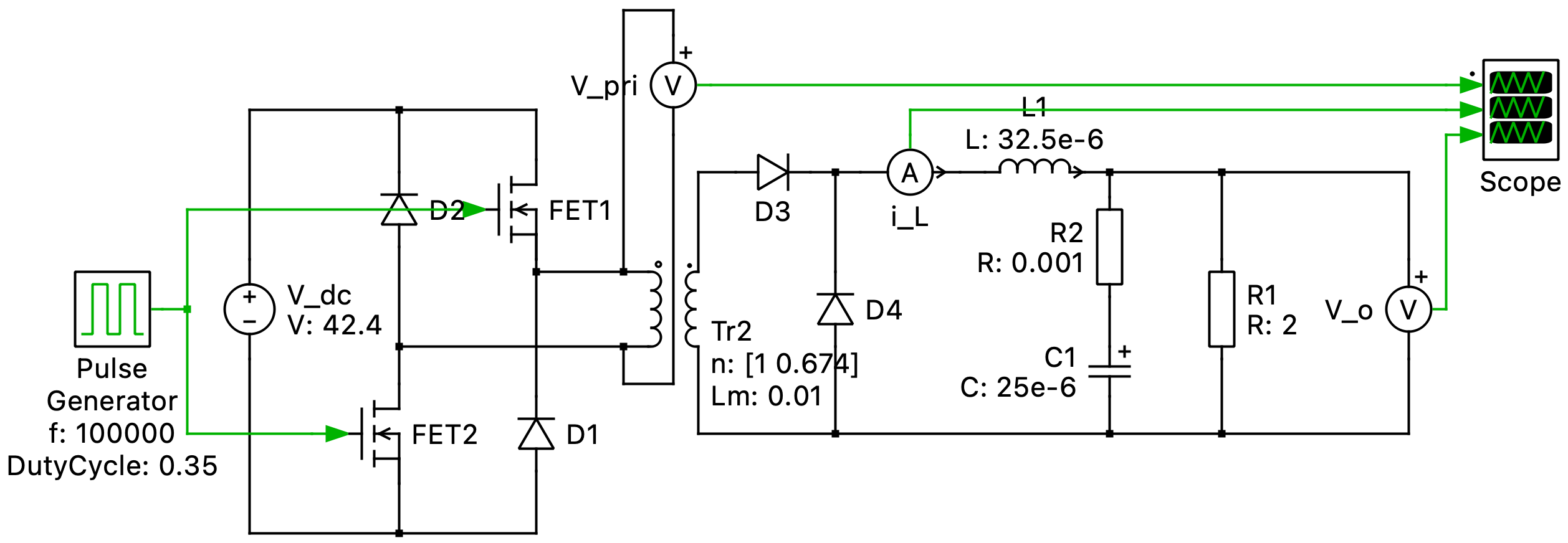
The design targets a 10 V, 5 A output. The report compares ideal and non-ideal PLECS models, transformer and inductor design, and Type I and Type III compensation. Magnetic components were characterised with an LCR bridge before open-loop and closed-loop measurements.
The power-stage diagram above shows the converter topology; it is not the full compensation circuit. The report uses the Venable K-factor method for the Type III compensator.
Reading the measurements
Under the report’s heavy-load AC test, Type I compensation shows a 100 Hz ripple envelope of 1.092 V. The Type III example reports 10.02 V output and 84 mV ripple. The two oscilloscope captures use different time scales: they illustrate the reported low-frequency behaviour and should not be treated as a direct comparison of switching spikes.
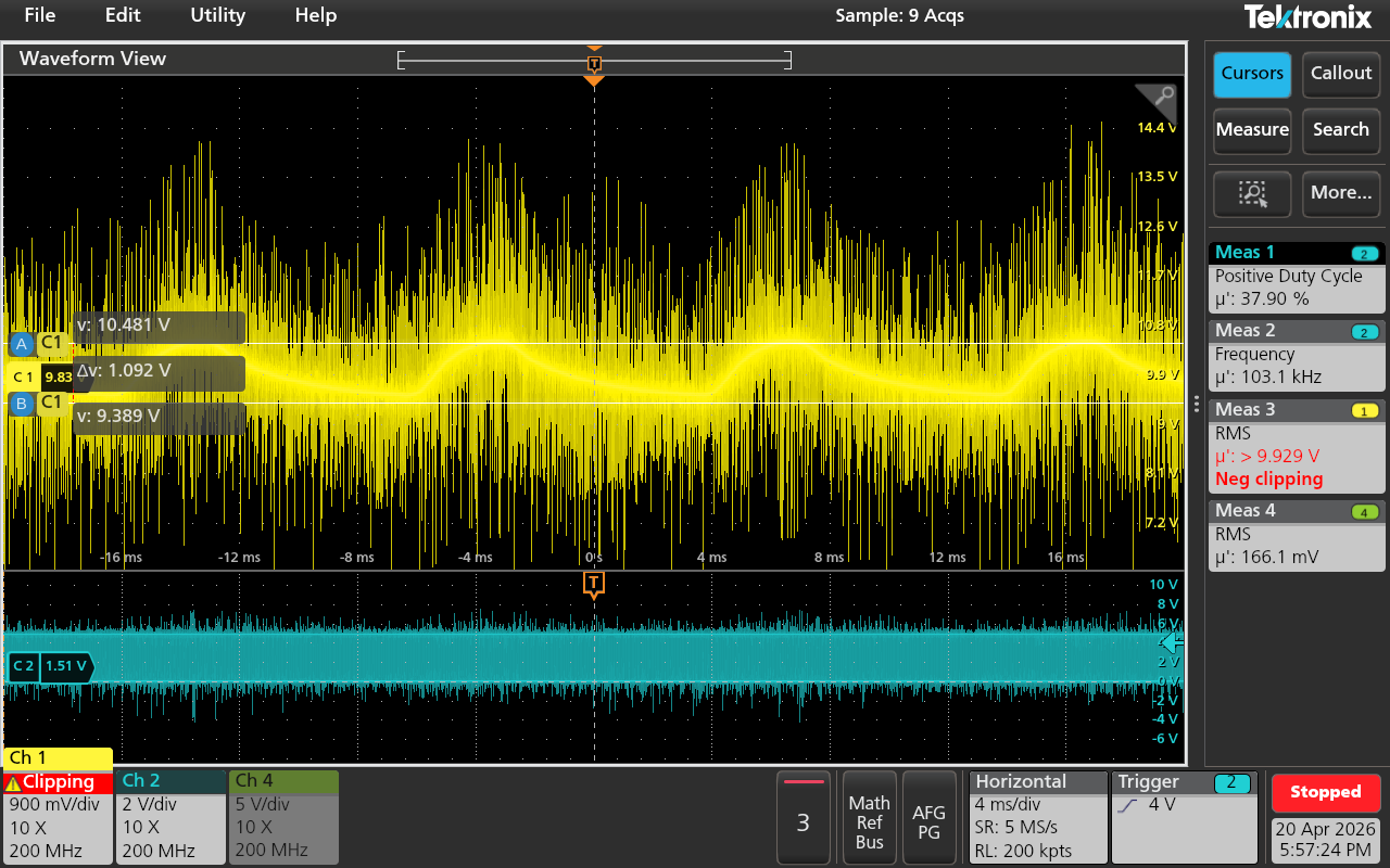
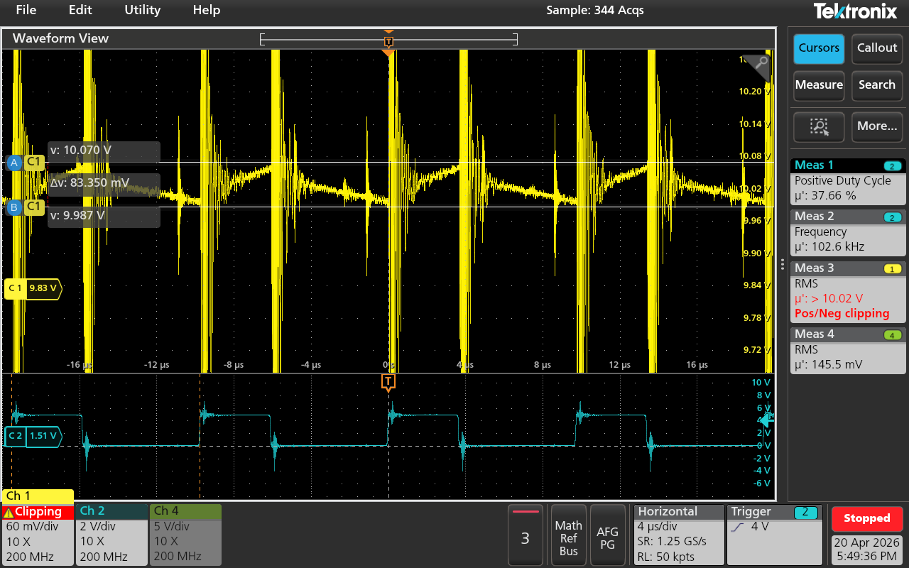
These are the team report’s measurements. Output ripple and high-frequency ringing are distinct; the report identifies parasitic effects and suggests snubber improvements.
Original record
Source: EEEE2074 Energy Project Group Report, Group 07, six pages. The author list is retained above. This page presents team design and reported measurements without assigning the complete converter to one person.
The full report includes the team’s email addresses and remains in the private archive. Selected figures are reproduced here without cropping or recolouring.