EEEE2075 · Group 02 · 2025
Doppler radar speed detector
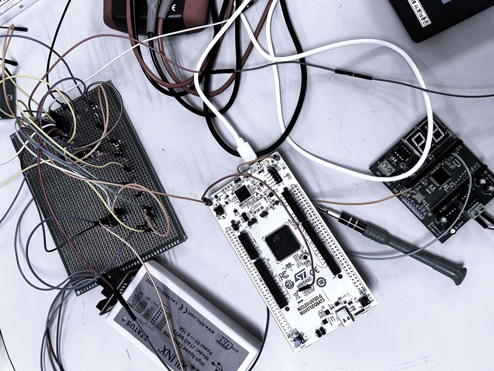
A signal-chain project connecting an HB100 radar, analogue conditioning, STM32 frequency processing and a CPLD display.
My contribution
Within Group 02, I worked on system integration, UART reception and display logic in Verilog, and oscilloscope-led investigation of thresholds and communication timing.
The team’s final presentation documents the team system; the role summary above follows my recorded project contribution.
From a weak signal to a display
The analogue front end amplifies and filters the radar output before ADC sampling. The STM32 estimates frequency using FFT processing, converts it to speed and sends formatted digits to the CPLD display. The integrated demonstration uses a 5 kHz sampling rate; the separate FFT exercise uses 10 kHz.

What the demonstrations show
The slides document a 2 kHz signal-generator exercise, a separate comparator-and-timer frequency counter, and a hand-motion radar demonstration. Noise thresholding and a low-frequency cutoff are used to stabilise the stationary display.
The stated 80 km/h range is a design objective, not a verified speed-accuracy result. Hand-motion examples are qualitative demonstrations rather than calibrated speed measurements.
Communication limitation: RS485 transfer remained one-way because the STM32 side lacked a transceiver. The slides identify a second transceiver and a PCB implementation as future improvements.
Original record
Source: Design and Implementation of Doppler Radar Speed Detector, Group 02 final presentation, 30 pages. The recovered Final Version was checked against the earlier slides; a final written report has not been recovered.
The original cover lists all four team members and student numbers. This page retains the team credit and selected original figures; the complete deck stays in the private archive.